1 Introduction
In artificial intelligence-driven times, antennas need to be stowed in limited environments before deploying regular operation in some applications, such as CubeSat or in-body detection. In these cases, antennas may be expected with acceptable gain in a compact size and enhanced gain in a deployed size. Therefore, reconfigurability has become an essential and desired feature for antennas to adapt to changing scenarios [1,2]. Reconfigurable antennas have been studied in the past three decades. Generally, reconfigurable antennas are classified into three categories: electrically [3–12], optically [13–15], and mechanically [16–37] reconfigurable antennas. With PIN diodes [3–5], radio-frequency microelectromechanical systems [6–8], or varactors [9–12], antenna performances can be reconfigurable in an electric manner. However, additional electrical components increase the system losses. Antenna reconfigurations relying on photoconductive switching elements are called optically reconfigurable antennas [13–15]. These reconfigurable systems suffer from high costs due to their optical components. Mechanically reconfigurable antennas are proposed for beam steering [16–19], polarization [20–22], frequency [23–27], or pattern reconfiguration [22,28,29], and reconfigurations are realized without the loss or cost of the electric or optical components. However, the reconfigurable antennas in Refs. [3–29] are not aimed at adjusting overall sizes in an extensive range to adapt to various environments changing during the operation.
Mechanically deployable antennas are proposed with reconfigurable sizes [30–37]. Deployable mesh reflector antennas [31,32] and log-periodic dipole antennas [33] are proposed with high broadside gain in a deployed state and stored in limited spaces without any radiation. Origami-inspired reconfigurable antennas are proposed in [34–37] and radiate with quite different patterns in compact and deployed states. To the best of our knowledge, few techniques can achieve high broadside gain in different reconfigurable sizes. Reversal sources are employed in compact antenna arrays to achieve super gains in the broadside direction [38–41]. Nevertheless, the designs in these types of literature are one-dimensional (1D), with fixed states, and are not reconfigurable.
This paper presents a gain-enhanced reconfigurable radiation array (RRA) in different reconfigurable sizes. As a demonstration case, the RRA has five elements in a 2D plane. With reconfigurable overall sizes and phase distributions among elements, enhanced gains can be realized theoretically in compact and deployed states. The size and phase distribution reconfiguration are achieved simultaneously with a proposed one-degree-of-freedom (1-DOF) deployable frame. Measured results show the enhanced gain of RRA, and the proposed RRA can be further extended to a large-scale array.
The remainder of this paper is organized as follows. First, the theoretical model of the proposed RRA is presented and analyzed theoretically. Next, we employ patch-based stacked antenna elements to compose the RRA and the 1-DOF deployable frame to realize the reconfiguration. In addition, we present the tessellation of the RRA for high-gain applications. We conclude with some final remarks.
2 Results
2.1 Theoretical model and analysis of RRA
Fig.1 shows the two types of schematic configuration of the RRA. The RRA consists of five ideal point sources (i.e., isotropic sources), with the same amplitude and works in compact and deployed states. The sizes of the RRA in the two types are set as D1 and D2. In Type I, the center element is out of phase (i.e., 180° phase difference, with four corner elements). On the other side, an in-phase center element is employed in Type II. The directivities of the two types of RRA against different size D are exhibited in Fig.2. When D is small, the directivities of the two types of RRA increase with D. The two traces peaked at D1 = 0.5λ0 and D2 = 0.8λ0 (λ0 is the wavelength in free space). Beyond the peak points, the directivity becomes lower again. When D is less than 0.6λ0, Type I is with a higher directivity; and beyond D = 0.6λ0, Type II’s directivity becomes the higher one. Therefore, the enhanced gain cannot be achieved in different sizes for arrays with a fixed-element phase distribution.


A detailed analysis is exhibited in Fig.3. The color in the 3D pattern represents the relative directivity. When RRA is compact in Type I, Fig.3(a) shows that the pattern of four corner elements has a wide beamwidth and low sidelobes. With the addition of the out-of-phase center elements (Case 1 in Fig.3(b)), the beamwidth becomes narrower. With the addition of the center elements, the sidelobes increase but are acceptable, and the antenna gain is enhanced. For Case 2 in Fig.3(c), after adding the in-phase center elements, the total pattern suffers from wider beamwidth and lower directivity. When the RRA is in a deployed size, high sidelobes and narrower beamwidth are observed in the pattern of the four corner elements, as shown in Fig.3(d). After adding the out-of-phase center element, the sidelobe becomes extremely high in the total pattern and results in lower directivity (Case 3), as shown in Fig.3(e). However, with the in-phase center element, the beamwidth becomes wider and the sidelobes decrease. Therefore, a higher directivity is achieved in a deployed size, as shown in Case 4 in Fig.3(f).

Fig.3 Theoretical analysis of the center antenna element effects on both states: (a) four corner elements in a compact size, (b) Case 1: out-of-phase center elements in compact size, (c) Case 2: in-phase center elements in compact size, (d) four corner elements in deployed size, (e) Case 3: out-of-phase center elements in deployed size, and (f) Case 4: in-phase center elements in deployed size. |
In summary, the enhanced gain is achieved by balancing the beamwidth and sidelobes. An enhanced-gain RRA can be achieved with an out-of-phase center element in the compact state (Case 1) and an in-phase center element in the deployed state (Case 4).
2.2 Realization of RRA
On the basis of the aforementioned theoretical analysis, the RRA is designed and simulated in ANSYS high-frequency structure simulator (HFSS). The RRA sizes are selected as 0.5λ0 in the compact state and λ0 in the deployed state. Therefore, each element size in RRA is limited to 0.25λ0 × 0.5λ0. The transformations of the element are shown in Fig.4. The Rogers 3010 with relative permittivity (εr) of 10.9 and thickness of 1.28 mm is selected as the substrate. The high-εr substrate miniaturizes the patch size to less than 0.15λ0. However, the conventional patch element in small size suffers from a low front-to-back ratio (FBR), which will result in a low gain. Four slots are cut on the ground, and two suspended substrates with stacked patches are employed as the directors based on the Yagi–Uda antenna design concept [42–44]. As illustrated in Fig.5, the element resonates around f0 (f0 is selected as 2.6 GHz in this design for 5G communication) with or without directors. Thus, the directors have a more negligible effect on S11 (scattering parameter from port 1 to port 1).


The directors’ effects on radiation patterns are exhibited in Fig.6. Without directors, the single-layer patch gain is only 4.31 dBi, with an FBR of 10.41 dB. After the addition of the directors, the gain and FBR are enhanced to 7.04 dBi and 15.14 dB, respectively. We use polyamide bolts and nuts to support the Director I. Polyamide has a relative permittivity of εr = 2.8 and dielectric loss tangent = 0.004. However, we also use polystyrene foam to support the Director II instead of other bolts and nuts. Polystyrene has a low relative permittivity of εr ≈ 1.1. Moreover, on the basis of our analysis, as shown in Fig.7, the single element resonates around f0 without or with a plastic bolt (f0 is set to 2.6 GHz in this design for 5G communication). The results indicate that the plastic bolt does not affect the reflection coefficient S11 and radiation pattern.


We employ the proposed directive element to compose the RRA. Cases 1′–4′ (corresponding to Cases 1–4 in Fig.3, respectively) are investigated, as shown in Fig.8. The center-to-center distances between the two adjacent corner elements are 0.5λ0 or λ0 in the two states. The arrows in the figure represent the polarization directions at a reference time. The red arrow indicates that the center element is out-of-phase with the four corner elements, and the blue arrow indicates that the center element is in the same phase as the other four.

The center element is 32.5 mm below the plane with four corner elements to enhance the isolation between the elements in a compact state to more than 22 dB. In the compact state, the gain of RRA in Type I (Case 1′) is 11.61 dBi, which is 1.39 dBi (37%) higher than the one in Type II (Case 2′), as shown in Fig.9. At the deployed state, Type II (Case 4′) becomes the better one with a gain of 12.68 dBi, which is 0.45 dBi (11%) higher than that of Type I. The results in Fig.8 coincide with the theoretical prediction in Fig.3. The RRA should be reconfigured from Cases 1′–4′ with size and phase distribution reconfiguration.

2.3 1-DOF mechanically deployable frame
On the basis of the discussion in Fig.7 and Fig.8, a mechanically deployable frame is designed to simultaneously realize the size and phase distribution reconfiguration, as shown in Fig.10. The frame has a mobile assembly of four planar four-bar linkages (i.e., L1–L4) on the xy-plane. Hence, this mobile assembly has one DOF [45,46] (i.e., only one kinematic input is required to switch the two instances). With the rotation angle φ from 0° (compact state) to 180° (deployed state), the center distance of the four corner elements is increased from 65 to 130 mm while rotating 180° relative to the center element. Take linkage L1 as an example. P1–P3 represent three types of rigid link. The central element is fixed to P1, the corner elements are linked to P2 with different orientations, and adjacent rigid links are connected by revolute joints. Linkages L1–L4 share a common rigid link P1 and are rotationally symmetric concerning it. Adjacent linkages share P2.

2.4 Measurement of RRA
With the proposed mechanically deployable frame, a prototype of the RRA is fabricated and measured, noting that the specific physical form of the rigid links can be optional as long as the axis position of the revolute joints is ensured. The frame is made of 3D-making plastic materials called acrylonitrile butadiene styrene (ABS). ABS is a terpolymer or a polymer composed of three monomers and has a relative permittivity of εr = 2.7.
An equal 1-to-5 power divider is designed to feed the proposed five-element RRA. Fig.11 shows the top view, dimensions, and port allocation. The divider is designed and fabricated on the RUILONG220 substrate with εr = 2.2 and thickness = 0.762 mm, as shown in Fig.12, with the comparison of the simulated and measured scattering parameters (S-parameters). The simulated S-paremeters are carried out as shown in Appendix A. Good agreement is observed. In the target frequency of f0, the reflection coefficient () of the input port is less than −25 dB. Transmission coefficients between the input port and five output ports ( and ) are all around −7 dB (close to 0.2) in simulation and −7.4 dB for measurement. Therefore, the loss of the power divider is around 0.4 dB and is further used to correct the measured gain. The mechanical frame is enclosed with a servo motor, which uses 1.5 V × 4 DC batteries to rotate from 0° to 180° (i.e., from the compact state to the deployed state).


The fabricated photos of the RRA at the two states and radiation pattern at the two cut planes (yz- and xz-plane) are measured by a near-field antenna pattern measurement chamber, as shown in Fig.13, where Fig.13(a) shows the compact state, and Fig.13(b) shows the deployed state). Simulated and measured in compact and deployed states are compared in Fig.14. Good agreement between the simulation and measurement is observed, and the proposed radiation RRA resonates at f0 for both states. The measured gain of the RRA is 11.66 dBi in the compact state and 12.25 dBi in the deployed state, with FBRs of more than 20 dB, as shown in Fig.15.


Fig.15 Simulated and measured radiation patterns in compact and deployed states: (a) comparison of simulated and measured radiation patterns at the compact state (yz-plane cut), (b) comparison of simulated and measured radiation patterns at the compact state (xz-plane cut), (c) comparison of simulated and measured radiation patterns at the deployed state (yz-plane cut), and (d) comparison of simulated and measured radiation patterns at the deployed state (xz-plane cut). Sim.: simulation, Meas.: measurement. |
To provide a full investigation of the rotation array, the bandwidth ( < −10 dB), broadside gain, and cross-polarization level (differences between GainPhi and GainTheta) against different rotation angles φ are shown in Fig.16. The resonant frequency of the RRA is almost unchanged during the rotation, as shown in Fig.16(a), and the measured average bandwidth is 0.983f0–1.013f0 (i.e., 2.55–2.63 GHz). As shown in Fig.16(b), the gain becomes higher with the increase of φ from 0° to 60°. Beyond φ = 60°, the gain is merely unchanged. The cross-polarization levels are lower than −30 dB at compact and deployed states because all elements are in parallel with one another. At other rotation angles, the cross-polarization levels become worse because the center element is not parallel with the four corner elements during the rotation. More detailed information of the S-parameters and radiation patterns for φ = 30°, 60°, 90°, 120°, and 150° are shown in Appendix B.

2.5 Tessellation of RRA
We remark that the proposed RRA is acceptable to be tessellated into large-scale arrays in mechanical and electromagnetic fields. The 2 × 2 RRA tessellation is investigated with 13 elements, as shown in Fig.17. On the basis of the fabricated RRA in Fig.13, Fig.17 presents the elements fixed to the extended mechanical frame. In addition to the rigid links mentioned above, P1–P3, we design two other types of rigid link, P4 and P5, optimized according to P1 and P2, to achieve a mobile assembly of 12 planar four-bar linkages of one DOF. The 2 × 2 RRA is of rotational symmetry, in which each pair of adjacent RRA shares two common links (i.e., P4 and P5) and two corner elements. With the additional two rigid links, the elements’ route during the rotation is reduced, which reduces the complexity of the connection between the RRA and the power dividers. The 2 × 2 RRA is constructed and measured.

A 1-to-13 unequal power divider is designed to feed the 2 × 2 RRA. The schematic of the 2 × 2 RRA with 13 elements at the deployed state is shown in Fig.18. Different from a single RRA, the 13 elements should be excited with different amplitudes. Element #7 is at the array center and shared by four RRA elements. Therefore, the relative excitation power of Element #7 should be 4, as indicated in the bracket. Similarly, Elements #2, #6, #8, and #12 are shared by two adjacent RRA, and the relative excitation power is set as 2. The remaining nine elements are excited with a relative power of 1. However, for the phase distribution, the proposed power divider has different branch dimensions categorized into three parts, as shown in Fig.19. The similar total lengths of different branches result in a similar phase distribution of the 13 elements.


Fig.19 shows the top views of the power divider with geometrical dimensions, and a photo of the fabricated 1-to-13 unequal power divider is inside Fig.20, with the simulated and measured S-parameters of the power divider. At f0, is less than −20 dB, which implies that the impedance match is achieved at Port 1 by the power divider. is almost 3 dB higher than , , , and , and 6 dB higher than the transmission coefficients between the remaining nine output ports and the input ports. Therefore, the amplitude distribution required in Fig.18 is achieved.

The fabricated photos of the 2 × 2 RRA at the two states are shown in Fig.21. The simulated and measured reflection coefficients of the compact and deployed states are shown in Fig.22. The radiation patterns at the compact and deployed states in the yz- and xy-plane cuts are shown in Fig.23. The proposed 2 × 2 RRA still resonates at f0 at all states, as shown in Fig.21. The measured gain of the 14.62 dBi in the compact state and 16.34 dBi in the deployed state is shown in Fig.23. In comparison with a single RRA, the gain is enhanced by 2.96 dBi at the compact state and 4.09 dBi at the deployed state.


Fig.23 Simulated and measured radiation patterns in compact and deployed states: (a) comparison of the simulated and measured radiation patterns at the compact state (yz-plane cut), (b) comparison of the simulated and measured radiation patterns at the compact state (xz-plane cut), (c) comparison of the simulated and measured radiation patterns at the deployed state (yz-plane cut), and (d) comparison of the simulated and measured radiation patterns at the deployed state (xz-plane cut). Sim.: simulation, Meas.: measurement. |
The bandwidth, gain, and cross-polarization levels against different rotation angles are compared in Fig.24. The measured average bandwidth for the proposed 2 × 2 RRA is 0.993f0–1.009f0 (i.e., 2.58–2.62 GHz). Similar to the single RRA, Fig.24(b) shows that the gain increases with φ from 0° to 60°. Beyond φ = 60°, the gain is merely unchanged. The cross-polarization levels are lower than −25 dB at compact and deployed states and become worse with other rotation angles. More detailed information of the S-parameter radiation patterns for φ = 30°, 60°, 90°, 120°, and 150° are shown in Appendix C.

3 Conclusions
In this work, we create a gain-enhanced mechanically RRA that works in compact and deployed configurations with phase distribution reconfiguration. A prototype of the RRA with a mechanically deployable frame is fabricated and measured to verify the design. The RRA can form a tessellation into arrays to obtain higher gains. It may be potentially applied in CubeSats systems. During the CubeSat launching or flight, the RRA can be stowed in a compact size and send some information with a relatively low data rate, such as position, velocity, or low-quality image. After the CubeSat arrives in the desired orbit, the RRA can be deployed, and it can send videos with a high data rate.
In addition, the theoretical model of the RRA is independent of the frequency. Thus, the proposed design can be potentially realized in terahertz or phonics frequency, with a miniaturized physical size. Therefore, the RRA can be a candidate for in-body detection. The RRA can be stowed in a capsule. After the capsule is swallowed, the RRA has a relatively low gain to maintain communication with the equipment outside the human body. When the capsule arrives at the stomach, the RRA can be deployed with enhanced gain to send high-quality images or videos. Then, the RRA can switch to a compact size again for the capsule to be excreted easily to outside the body.
4 Appendixes
4.1 Appendix A Single simulated S11 in AWR microwave office
An RRA includes three parts, namely, the power divider, cables, and antenna array. Simulating all three parts together is difficult. Therefore, we initially simulate the power divider and the antenna array in the HFSS separately. Next, we measure the cables by VNA. Then, we export the SNP file to AWR microwave office. N is the port number. For example, N = 2 for cables, N = 5 for a 5-element array, and N = 6 for a 1-to-5 power divider. Then, we can obtain the combined simulated reflection coefficient , as shown in and .


4.2 Appendix B Single RRA rotation angle φ
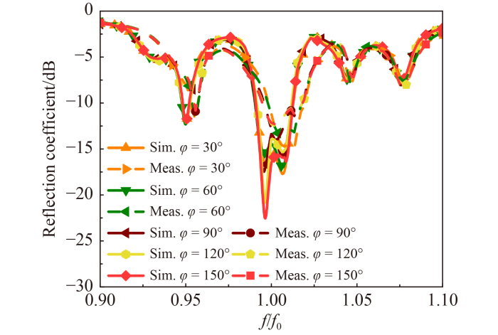
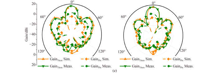
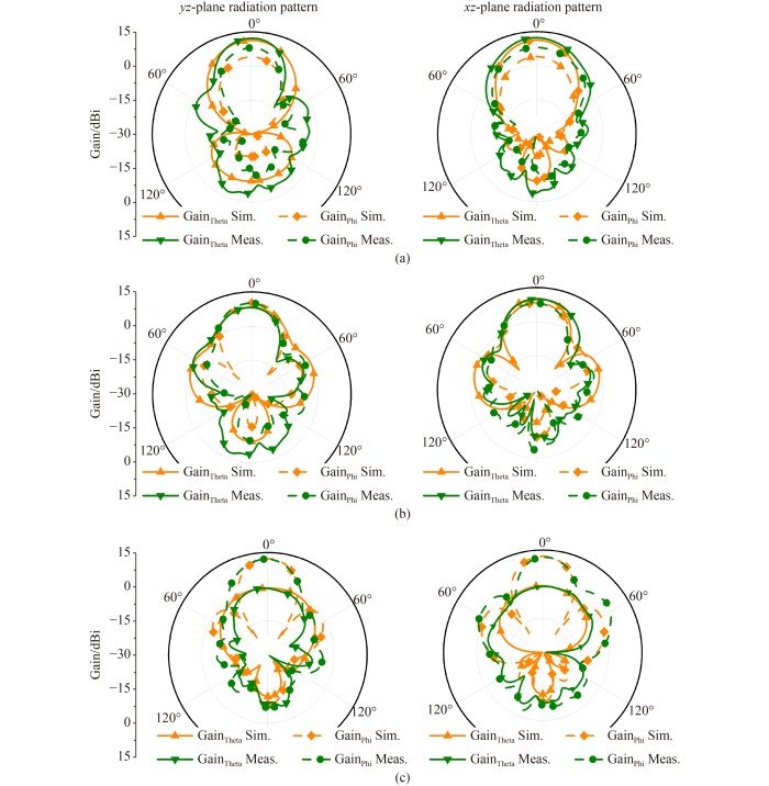
This appendix shows how we perform a sensitive investigation at different rotation angles φ apart from 0° and 180° in compact and deployed states. The RRA agrees with the aforementioned theory and can achieve a higher gain with an unchanged reflection coefficient (). The simulated and measured reflection coefficients () at φ = 30°, 60°, 90°, 120°, and 150° are shown in , and shows the simulated and measured radiation patterns for the yz- and xz-plane at φ = 30°, 60°, 90°, 120°, and 150°. Agreement between the simulation and measurement is observed.


4.3 Appendix C 2 × 2 RRA rotation angle φ
This appendix shows how we perform a sensitive investigation on a 2 × 2 array at different rotation angles φ apart from 0° and 180° in compact and deployed states. We validate the aforementioned theory and show that we can achieve a higher gain with an unchanged reflection coefficient (). The simulated and measured reflection coefficients () at φ = 30°, 60°, 90°, 120°, and 150° , as shown in , and shows the simulated and measured radiation patterns for the yz- and xz-plane at φ = 30°, 60°, 90°, 120°, and 150°. Agreement between the simulation and measurement is also observed.