

1 Introduction
Natural gas (NG) plays an increasingly important role in global energy in recent years, with the advantages of cleanliness, efficiency, economy, and safety. Liquefied natural gas (LNG), whose volume is about 1/625 of the initial NG, can be obtained through the liquefaction processes, which makes it convenient to be transported by ships and trucks. In 2019, the global LNG trade volume reached 354.73 MT (million tons), increasing 40.93 MT compared to that in 2018. Correspondingly, there are over 130 receiving terminals worldwide with a total regasification capacity of 821 MTPA (million tons per annum) till February 2020 [1].
LNG vaporizers are essential equipment for the process of gas delivery in LNG receiving terminals. The terminals, which receive the LNG transported by ships, are always built along the coast. Accordingly, seawater is the most common heat source because it is free, abundant, easily available, and inexhaustible. The LNG vaporizers, which utilize seawater as the heat source, can be classified into the open rack vaporizer (ORV), the super open rack vaporizer (Super-ORV), and the intermediate fluid vaporizer (IFV) according to their different structures.
In the ORV, the seawater flows uniformly outside the tubes from the spray device to directly provide heat for the LNG inside the tubes. The structure and working principle in the Super-ORV are similar to those in the ORV, except for some changes in the heat transfer tubes [2]. The IFV, first proposed by the Osaka Gas Company [3], is more complicated than ORV. The typical structure and operating process of IFV are shown in Fig. 1. Generally, the IFV is composed of a vaporizer (E1), a condenser (E2), and a thermolator (E3), which are all shell and tube heat exchangers. The intermediate fluid (IF) is in the shell side of E1 and E2. After being vaporized by seawater in the tube side of E1, it will rise into E2 and then be condensed by the supercritical LNG in the tube side of E2. The seawater flows through the tubes in E3 and E1 with a temperature drop. At the same time, the supercritical LNG obtains heat from the intermediate fluid and seawater in the tube side of E2 and the shell side of E3, respectively. By the process above, LNG is heated and gasified above 0°C for the following output. The heat transfer characteristics of the supercritical LNG flowing inside the tubes and the intermediate fluid condensing outside the tubes in the unit E2, are quite different from other types of LNG vaporizers. Therefore, the heat transfer process in E2 is one of the key issues in the studies and development of IFV.

There are many advantages of adopting IFV in receiving terminals compared with other LNG vaporizers. First, there are no negative effects of seawater freezing in IFV, since heat is transferred between seawater and LNG through the intermediate fluid. In addition, the seawater tubes are made of titanium alloy, which has a superior performance in resisting the corrosion of seawater and the abrasion of sand. Moreover, the heat transfer efficiency is improved by the phase change heat transfer of the intermediate fluid [4]. Furthermore, IFV has also been widely used in circulating heating systems, offshore floating storage and gasification systems, and cold energy power generation systems [5,6].
In this present paper, studies of IFV are systematically reviewed, including the structural innovation design, thermal calculation model, and selection of different intermediate fluids. Moreover, the investigations of the heat transfer involved in the vital unit E2 are summarized, including the fluid flow and heat transfer of the supercritical LNG inside the tubes and the condensation heat transfer of the intermediate fluid outside the tubes. The research methods mentioned include theoretical analysis, experimental investigation, numerical simulation, and process simulation. After the analysis of the current research status, the shortcomings in the thermal calculation model and the experimental investigation and numerical simulation on the condensing heat transfer process of the intermediate fluids are summarized. Then, further studies on IFV and its heat transfer characteristics are suggested.
2 Structural innovation design
The traditional IFV is mainly composed of three shell and tube heat exchangers. For energy saving, economy, safety, and cold energy utilization, different new structure designs and performances were compared. A new structure of IFV, suitable for the floating storage and regasification unit (FSRU), was designed and developed, and its feasibility was verified [7]. Spiral wound tube heat exchangers instead of shell and tube heat exchangers in E1 and E2 were proposed for saving consumables. At the same time, a pump set was added for the circulation of intermediate fluid between E1 and E2 to increase the start-up speed and reduce the influence of non-condensable gas. For offshore operation, Liu et al. [8] designed a device for the prevention of liquid level shaking and verified its feasibility by experiment. In this device, some partitions were placed in the shell side of IFV to divide the intermediate fluid into several zones, and the sloshing amplitude of the entire liquid surface was reduced. As a result, the dry burning of the tubes in E1 caused by the liquid level sloshing and the heat transfer failure of the tubes in E2 caused by the splash liquid covering could be avoided. A compact metal foam plate heat exchanger was adopted in E3 by Kim et al. [9], and the heat transfer efficiency was improved while the volume of the heat exchanger was reduced. According to the thermal calculation results, the IFV with the new structure had a higher heat transfer performance, a lower pressure drop, and a lower power consumption, and this advantage was more significant with the increase in the flowrate of LNG. Similarly, Wang et al. [10] proposed a novel multi-stream plate-fin intermediate fluid vaporizer (MPFHE-IFV), in which E2 and intermediate fluid were replaced with a plate-fin heat exchanger and self-evaporating gas of low-temperature fluid, respectively. The structure and configuration of MPFHE-IFV were demonstrated in Fig. 2. After the optimization of its structural layout, the new device could avoid freezing at low temperatures while improving the heat transfer efficiency. In addition, the MPFHE-IFV could be conveniently combined with a cold energy recovery system. Moreover, Wang et al. [11] proved that the SIFV (the simplified IFV without thermolator E3) was capable of vaporization under low load conditions by thermal calculation. The function of the thermolator under the operating condition of the research was summarized in Table 1, in which T2 and T3 referred to the inlet and outlet temperature of NG in E3 respectively. As can be observed from Table 1, the thermolator was unnecessary under the low load operating condition, since the temperature of NG was above 0°C. Even when T2 was below 0°C at a load of 100 t/h, the proportion of the heat exchanged in E3 was less than 3%, while there was more than 40% of pressure loss in E3. Therefore, compared with the traditional IFV system, SIFV could save initial investment, reduce pressure drop, and system power consumption in E3, and prevent seawater from freezing in E3.

Tab.1 Function of thermolator in operation [11] |
| Load/(t∙h–1) | T2/°C | T3/°C | Total heat exchange/MW | Heat exchange in thermolator/kW | Total pressure drop/kPa | Pressure drop in thermolator/kPa |
|---|---|---|---|---|---|---|
| 100 | –0.40 | 6.46 | 19.84 | 566.88 | 71.89 | 31.21 |
| 90 | 0.59 | 6.79 | 17.92 | 379.32 | 58.01 | 25.18 |
| 80 | 1.49 | 7.01 | 15.98 | 283.77 | 45.96 | 19.87 |
| 70 | 2.31 | 7.12 | 14.03 | 254.24 | 35.29 | 15.22 |
| 60 | 3.11 | 7.34 | 12.06 | 218.43 | 25.23 | 11.80 |
3 Overall thermal calculation
To meet the requirements of engineering design and optimization, an overall thermal calculation model for the IFV system should be first established. The overall performance of the vaporizer and the feasibility of the scheme can also be verified by the thermal model, which is mainly based on the energy balance relationship and heat transfer characteristics of E1, E2, E3 and the whole IFV system. In addition, key parameters such as the required heat transfer area (HTA), the outlet parameters of the working fluid, and the saturation temperature of the intermediate fluid can be obtained by numerical iteration. Moreover, the effects of practical factors have been considered by researchers to improve calculation accuracy, including the establishment of a distributed parameter model (DPM) in consideration of the dramatic changes in physical properties along the tube, and the use of modified heat transfer correlations in consideration of the bundle effect and bubble disturbance.
3.1 Thermal calculation model
Bai et al. [12] adopted a method for calculating the HTA of IFV. In this method, a thermal calculation model of IFV with propane as the intermediate fluid was established, and the calculation was based on the energy conservation and heat transfer correlations of the three parts. The HTA, the distribution of state parameters, and the heat transfer coefficient (HTC) were obtained. Similarly, knowing the structural parameters of IFV, the distributions of temperature and HTC were obtained by Pu et al. [13]. The effects of the inlet temperature and the flowrate of seawater, the inlet pressure and the flowrate of LNG on the heat transfer performance of the system, and the saturation temperature of the intermediate fluid were also studied. Based on the above analysis, the connections between the internal parameters of the system were revealed. In view of the dramatic change of LNG temperature along the process, Xu et al. [14] segmented the tubes in E2 along the flow direction according to the principle of equality in temperature rise. Then, a one-dimensional distributed parameter model was established for the subcritical IFV, and the flow boiling characteristics in different zones of the LNG tubes were predicted. Additionally, the effects of the main parameters, such as the inlet temperature of seawater, the inlet pressure, and the flowrate of LNG, on the heat transfer performance and HTA were studied.
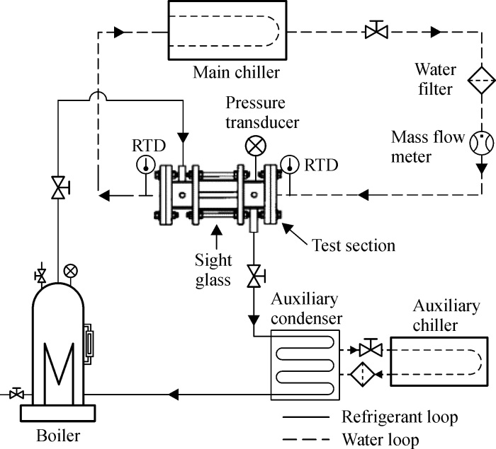
It should be noted that practical factors such as bubble disturbance and bundle effect were usually ignored, therefore, the same heat transfer condition for different tube banks was assumed. In fact, the practical factors mentioned above significantly impact the calculation of heat transfer characteristics and the system design. Higashi et al. [15] considered the effects of the rise of bubbles in E1 and the splash of liquid in E2 when selecting the heat transfer correlations. The method was adopted in the calculation model, and the results were compared when using different pool boiling correlations. In addition, a laboratory-scale IFV system was built to verify the prediction accuracy of the model, as illustrated in Fig. 3. The experimental investigation was performed with hot and cold water as the heat and cold sources. Then, the HTCs of propane, R32 and R410A under the experimental conditions were obtained. It was found that the HTCs of R32 and R410A were significantly higher than those of propane.

3.2 Heat transfer correlations
In the thermal calculation model, the HTC and heat flux of each part are predicted by the empirical or semi-empirical heat transfer correlations. According to the characteristics of different processes in IFV, the heat transfer correlations used by different scholars in each heat transfer segment are summarized in Table 2.
Tab.2 Heat transfer correlations in IFV thermal model |
| Units | Segments | Heat transfer correlations | References | ||
|---|---|---|---|---|---|
| E1 | Seawater inside the tube | Ref [16] | |||
| Intermediate fluid outside the tube | Single tube | Ref [17] | |||
| Ref. [18] | |||||
| Ref [19] | |||||
| Ref [20] | |||||
| Ref [21] | |||||
| Ref [22] | |||||
| Tube bundle | Ref [20]. | ||||
| E2 | Supercritical LNG inside the tube | Ref. [23] | |||
| Ref. [24] | |||||
| Intermediate fluid outside the tube | Single tube | C= 0.725 C= 0.729 C= 0.79 | Ref. [25] Ref. [26] Ref. [27] | ||
| Tube bundle | Ref. [28] | ||||
| Ref. [29] | |||||
| E3 | Seawater inside the tube | Ref. [16] | |||
| Supercritical NG in shell | Ref. [30] | ||||
As can be observed from Table 2, the correlations selected by different scholars were relatively consistent in the heat transfer calculations for seawater and LNG. However, there were different choices of correlations in the calculations of the condensation and gasification of intermediate fluids. The consideration and correction of the bundle effect and bubble disturbance were also different. Four pool boiling correlations were adopted by Higashi et al. [15] in the calculation of HTCs, and the results were presented in Fig. 4. It was exhibited that the choice of correlations had a great influence on the performance calculation and the design of the IFV. Unfortunately, there is almost no accuracy assessment of different correlations for IFV.

4 Different intermediate fluids
As the medium of heat transfer between LNG and heat source, the types and working states of intermediate fluids have a significant impact on the overall heat transfer and the structural design of the system. In general, there are several constraints on the above selections. First, the saturation temperatures of the intermediate fluids must be higher than –160°C since the inlet temperature of LNG is around –160°C. Besides, it should be ensured that the intermediate fluids and the seawater in E1 and E2 will not freeze. At the same time, the temperature of LNG at the outlet of E2 should not be too low in order to prevent the seawater in E3 from freezing. In addition, the intermediate fluids should also have characteristics such as high latent heat, high heat transfer performance, low ODP, and low GWP [15]. Considering the above limitations, the candidates for the intermediate fluids are mostly Freons, hydrocarbons, and hydrocarbon derivatives in current investigations. The pure working fluids adopted in studies and their saturation temperatures at atmospheric pressure are listed in Table 3. Moreover, the mixed working fluids considered are mostly hydrocarbon mixtures or mixtures of the working fluids.
Tab.3 Pure working fluids and their saturation temperatures at atmospheric pressure |
| IF | /K |
|---|---|
| R1270 | 225.53 |
| R290 | 231.04 |
| R600a | 261.40 |
| R600 | 272.66 |
| DME | 248.37 |
| R134a | 247.08 |
| R22 | 232.34 |
In a typical IFV, the intermediate fluid connects the heat transfer process between the heat source and LNG by vaporization and condensation. In a certain temperature range, Xu et al. [31] calculated the HTAs of the IFVs by thermal models using five different intermediate fluids. It was found that in addition to the widely used propane, propylene and dimethylether (DME) were also promising in the IFV, from the perspective of heat transfer and saturation pressure. Han et al. [32] studied the effects of seven refrigerants on heat transfer in a wide range of saturation temperatures by establishing a one-dimensional distributed parameter model. The required total HTA for different refrigerants was depicted in Fig. 5. It can be seen that the system using propylene as the intermediate fluid led to the minimum HTA, followed by propane and DME. However, there was a limitation to the application of propylene because of the high saturation pressure, which meant the increase in the shell thickness. The required HTA with DME as the intermediate fluid was lower than that with propane when the saturation temperature was lower than 269 K. Therefore, considering the heat transfer efficiency and saturation pressure, DME and propane was the best candidate when the saturation temperature was below and above 269 K, respectively. In addition, a wider range of optimal saturation temperature could be obtained by increasing the seawater temperature. Moreover, the heat transfer performances of the systems using different mixtures as the intermediate fluids were analyzed by Yan et al. [33]. The mixtures of ethane and propane as well as butane and propane were better choices compared with propane from the perspective of heat transfer and saturation pressure. For diverse operating environments, the IFV systems using the less flammable refrigerants R32 and R410A were proposed by Higashi et al. [15]. It was proved by thermal models that the above systems had a better heat transfer performance than that used propane. As a result, a higher vaporization capacity of the systems using R32 and R410A was suggested. Wang et al. [34] conducted a similar study to analyze the effect of saturation temperature on the heat transfer performance when a mixture was used as the intermediate fluid. Then, combined with the analysis of the sensitivity to the fluctuation of seawater temperature, the optimal saturation temperature of the mixed intermediate fluid was obtained. In general, studies for the selections of intermediate fluids and their working states were based on the overall thermal model. The experimental tests and numerical simulation calculations of the condensation heat transfer of intermediate fluids outside the tubes will be reviewed in Section 6.

For reducing the size of the equipment in FSRU, a special IFV system where the intermediate fluid was always in a subcooled state was proposed. Ji et al. [35] studied the subcooled IFV system with glycol solution as the intermediate fluid by process simulation and designed two heat exchangers of the system by thermal calculation. It was found that, compared with that using propane as the intermediate fluid, the process using glycol solution had the advantages of a smaller HTA, less circulation of the intermediate fluid, a lower power consumption of the pumps, a lower operating pressure, and a better economic performance. They also built a double-tube experimental platform to conduct experiments on the heat transfer process between subcooled propane and water, and to explore the heat transfer characteristics of propane under static horizontal and inclined conditions [36]. It was discovered that there was an increase in HTC when the sea level shook slightly. The experimental results were then compared with those of the existing heat transfer correlations, and the correlations with higher accuracy were selected. Moreover, a numerical simulation calculation on the heat transfer process between subcooled propane and seawater in E1 was performed by Song et al. [37], and the effects of the inlet temperature and the flowrate of seawater on the heat transfer characteristics were obtained.
In summary, several alternative working fluids have been considered by the researchers. The candidates included Freon and hydrocarbons, which are commonly used in the refrigeration and air-conditioning field, hydrocarbon derivatives similar in physical properties to propane, and the mixtures of the fluids mentioned above. Usually, considering the indexes like heat transfer efficiency and saturation pressure, working fluids under different working conditions have also been selected through overall thermal calculations.
5 Heat transfer of supercritical LNG in heated tubes
Methane is the main component of LNG, of which the critical pressure and temperature are 4.60 MPa and –82.59°C respectively. Usually, the temperature of LNG at supercritical pressure during the vaporization process in the tubes of E2 rises from about –160°C to above 0°C, which is called transcritical fluid flow [38]. Different from subcritical flow, there is no phase change for the LNG in the tubes of E2. However, the thermophysical properties change drastically near the pseudocritical temperature, as displayed in Fig. 6. As temperature rises, the density, the viscosity, and the thermal conductivity of supercritical methane decrease continuously, especially with sharp drops near the critical point. There is a peak for the specific heat at the pseudocritical point, which reaches the highest at the critical point. As pressure increases, the magnitude of the peak decreases with the pseudocritical temperature rising, and the rates of the changes for the properties slow down. Moreover, supercritical fluid exhibits some properties and advantages of gas and liquid, such as liquid-like density and gas-like diffusivity, which have a positive effect on solubility and fluid transportation [39].

As a result, the supercritical heat transfer characteristics are very different from those of the conventional single-phase and phase-change processes. Therefore, for evaluating the accuracy of the existing heat transfer correlations, it is essential to study the heat transfer characteristics of supercritical LNG in heated tubes, which can also provide suggestions for selections of correlations in thermal designs of IFV. In addition, the above studies also have a referential value for the enhancement of heat transfer and the optimization of the whole system, which makes it possible to reduce the size of the equipment, reduce investment and energy consumption, and ensure the safe and stable operation of the system.
5.1 Heat transfer of supercritical LNG in the cooling jacket
Studies on supercritical heat transfer were mostly focused on fluids such as water, carbon dioxide, and nitrogen [40–44]. Studies on the heat transfer of supercritical methane in the heated tubes first appeared in the relevant literature of the engine cooling channel. In the engine using methane as the fuel, methane is usually used as a coolant in the regenerative engine-cooling process before fuel injection and combustion. A numerical study on the heat transfer of supercritical methane in a horizontal minitube was conducted by Wang et al. [23], and the heat transfer deterioration near the pseudocritical temperature region was discovered. Then, they explored the effects of inlet temperature, inlet pressure, inlet velocity, and wall heat flux on the heat transfer. Finally, an experimental heat transfer correlation of the supercritical methane in the tube was obtained by modifying the correlation of Jackson and Hall [24], as listed in Table 2, which used supercritical carbon dioxide and water as working fluids. Because the Jackson and Hall correlation makes a good prediction of the heat transfer characteristics near the pseudocritical temperature, it has been widely used in the current thermal calculations of IFV. Xu et al. [45] also conducted a numerical simulation on the heat transfer of supercritical methane in ribbed cooling tubes. They further explored the effects of rib geometry, rib height, thermal conductivity, and heat flux on heat transfer and pressure drop. It was found that the heat transfer performance of the ribbed tube was significantly enhanced than that of the smooth tube, because of the weakened heat transfer deterioration, especially under a higher heat flux. Liang et al. [46] obtained another heat transfer correlation by the fluid flow and heat transfer experiments of working fluids such as methane, ethane, and No. 21 high-density kerosene at 0.5–20 MPa in stainless steel tubes and copper tubes. Besides, Ricci et al. [47] conducted experimental and numerical investigations on the supercritical heat transfer process of methane in a rectangular single channel, representative of the cooling jacket of a rocket engine. The experiment was conducted on the MTP-BB (methane thermal properties breadboard), and the data at different inlet pressures and temperatures were obtained. The results of the numerical simulation study agreed well with the experimental data. Moreover, they also observed the thermal stratification and the deterioration of heat transfer in the simulation.
5.2 Heat transfer of supercritical LNG in LNG vaporizer tubes
Numerical simulations on the heat transfer of supercritical methane in the tubes have been conducted under LNG vaporizer operating conditions. Yao et al. [48] established a numerical simulation model for a U-shaped tube with a length of 6m. The effects of the flowrate and the pressure of LNG on the heat transfer process were analyzed. A similar transient computational fluid dynamics (CFD) model of supercritical LNG heat transfer in a horizontal single tube and tube bundle of an IFV was established by Xu et al. [49,50]. In the study of single tube, the effects of the inlet pressure and the flowrate of LNG on heat transfer and the predictive accuracy of various heat transfer correlations under different flowrates of LNG were investigated. In addition, the buoyancy played a non-negligible role in the heat transfer process under the entire range of working conditions in the study. The effect of LNG component was also studied, and it was found that the LNG component had a great impact on heat transfer performance and output parameters of IFV, suggesting that the influence of LNG component should be considered for a more reliable design of IFV. Simultaneously, the CFD simulation results were compared with those of the one-dimensional distributed parameter model, which showed a smaller difference for the tube bundle than for the single tube. Cheng et al. [2,51] established a numerical simulation model for the heat transfer between LNG and seawater in the vertical smooth tube and rib tube of ORV. The results of numerical simulation and thermal calculation were compared, and the effects of different parameters, such as pressure, flowrate and temperature, on the heat transfer performance of the system were also explored. In summary, numerical simulations on the fluid flow and heat transfer of supercritical LNG in the vaporization tubes have been conducted on the effects of inlet temperature, pressure, flowrate, and LNG component. Meanwhile, new heat transfer correlations for predicting the HTCs of supercritical fluid in the smooth tube and rib tube were developed based on the numerical simulations and the existing correlations. The heat transfer performances of single tube and tube bundle were also calculated and compared by different researchers. In terms of experiments, no vaporization experiment of supercritical methane under IFV operating conditions has been reported, except experiments for ORV operating conditions [52].
6 Condensation heat transfer of intermediate fluids outside tubes
As intermediate fluids, the refrigerants condense outside the LNG tubes in E2. As mentioned in Section 4, the candidates for the intermediate fluid are all freons, hydrocarbons, and their mixtures in current studies. Both theoretical or semi-empirical models for the condensation heat transfer outside the tubes have been established [26,53–55]. For example, Al-Badri et al. [56] proposed an element by element prediction model of condensation on a finned tube. To verify the accuracy of the model, the distributions of temperature and HTC for propane and R134a were compared with the experimental data. However, the theoretical models of condensation outside the tubes are usually established by simplifying the problems with assumptions. As a result, the widely applied theoretical models are difficult to simultaneously maintain a high precision and versatility. In addition, it is known that the physical properties of refrigerants are quite different from those of the commonly studied fluids such as water. Therefore, experimental studies and numerical simulations on the condensation heat transfer of freons and hydrocarbons have been conducted.
6.1 Experiments of condensation outside tubes for refrigerants
At present, numerous experimental studies have been conducted on the condensation outside tubes for freon and hydrocarbons. The key parameters of the experiments are summarized in Table 4.
Tab.4 Experimental studies on condensation outside tubes for refrigerants |
| References | Types of tubes | Working fluids | Saturation temperatures/°C |
|---|---|---|---|
| Refs. [27,57,58] | Plain, low fin and Turbo-C tubes | R11, R12, R22, R407C, R410A, R32, R1270, R290, R600a, R600, RE170 | 39 |
| Ref. [59] | Low fin and Turbo-C tubes | R1270, R290, R600a, R600, RE170, R32 | 39 |
| Ref. [60] | Smooth, standard finned and high performance tubes | R290, R134a | 37 |
| Refs. [61,62] | Smooth and integral fin tubes | R600a | 32.17–39.19 |
| Ref. [63] | Plain and enhanced titanium tubes | R134a, R1234ze(E), R290 | 35–40 |
| Ref. [64] | Plain tube | R290 | 1.73–13.4 |
| Refs. [65,66] | Plain tube | R290, R170 and R290 | 26.94, 20.4–34.2 |
| Ref. [67] | Standard finned and enhanced finned tubes | R134a | 37 |
| Ref. [68] | Smooth and enhanced tubes | R410A | 35–45 |
| Ref. [69] | Smooth and enhanced tubes | R134a, R1234ze(E), R1233zd(E) | 38 |
| Ref. [70] | Smooth and enhanced tubes | R134a | 45 |
The freons or hydrocarbons mentioned above are either eliminated refrigerants or alternative refrigerants that are more environmentally friendly in the refrigeration and air-conditioning field. Therefore, as presented in Table 4, the saturation temperatures were mostly between 30°C and 45°C in the experiments. As shown in Fig. 7, an experimental platform was built by Jung et al. [27,57,58], in which the vapor condensed through a counter-current heat exchanger with the cooling water inside the tube. In addition, the other experimental devices to be discussed below were similar to this apparatus. The condensation heat transfer processes of 11 refrigerants including propane outside the plain tubes and 5 refrigerants outside the low-fin tubes and Turbo-C tubes were investigated in this experiment. The relationship between the condensation HTCs of 8 refrigerants and wall subcooling was plotted in Fig. 8. All refrigerants showed that the condensation HTC decreased with the increase of wall subcooling, while R32 had the highest HTC among the tested refrigerants. Finally, the heat transfer correlation of Nusselt’s theoretical solution [25] was revised, and a new correlation for condensation heat transfer outside the tube was obtained based on the experimental data, of which the fitting deviation was within 3%, as tabulated in Table 2. Park and Jung [59] experimentally studied the condensation heat transfer of 6 flammable refrigerants, including propane, outside the low-fin tubes and Turbo-C tubes. It was found that the HTCs calculated by the correlation developed by Beatty and Katz [71], which predicted the condensation HTC outside the low-fin tubes, were lower than the present data due to the lack of consideration of surface tension. It was evident that Turbo-C tubes had a better condensation heat transfer performance compared with the low-fin tubes. Gebauer et al. [60] conducted a similar experiment for the condensation of propane and R134a outside the smooth tubes, standard finned tubes, and high-performance tubes, of which water was the cold and heat source. It was worth mentioning that both single tubes and tube bundles were studied in the heat transfer performance. Then, the experimental data were compared with the results of theoretical calculation models and CFD simulations. Derived from the additional structure that was not conducive to the drainage of condensates, the high-performance tube showed a greater bundle effect compared with the standard finned tubes, though it performed better in heat transfer. At the same time, it was also found that the effect of the coating in increasing the thermal resistance was greater than that in reducing the surface free energy. As a result, the HTC was reduced while the bundle effect could not be reduced by coating. Sajjan et al. [61,62] conducted a visual experimental investigation of the condensation heat transfer characteristics outside the horizontal smooth tube for R600a at different pressures and wall subcooling temperatures. It was found that the HTC could be improved by increasing the saturation pressure or reducing the wall subcooling temperature. The HTC predicted by Nusselt’s theoretical solution was lower at a high pressure and higher at a low pressure than the experimental data. Meanwhile, a similar experimental study was conducted on fin tubes with different fin densities. Then, the fin density with the highest HTC was obtained, and the functional relationship between heat flux and wall subcooling temperature was obtained for different fin densities. Finally, a comparison was made between different theoretical correlations and experimental data, and the explanations for the deviations were given. Ji et al. [63] performed an experiment to investigate the condensation heat transfer characteristics of three refrigerants, including propane, outside the smooth tubes, and the enhanced titanium tubes. The effects of heat flux, refrigerant, and saturation temperature on the HTC were discussed. It was shown that the condensation HTCs at the saturation temperature of 35°C were similar to that at 40°C for R134a and R1234ze(E). However, it was worth mentioning that, for propane, the HTCs of condensation on the enhanced tube increased with the increase of saturation temperature, while the opposite was true on the smooth tube. The experimental data and the results calculated by five heat transfer correlations, which predicted condensation outside the enhanced tubes, were also compared in this study. The calculated values of the correlations had large deviations from the experimental data, of which the smallest was between –42.3% and –14.8%. Chen et al. [64] conducted boiling and condensation heat transfer experiments for propane in two sleeve-type smooth circular tubes, where nitrogen and water were used as cold and heat sources, respectively. In addition to common factors such as the inlet temperature and the flowrate of water, the effect of the inclination of the tube on the heat transfer of propane was investigated. Finally, the deviations between the existing boiling and condensation correlations and the experimental data were plotted. Moreover, several studies on mixed working fluids were conducted. For example, Pang and Mi et al. [65,66] experimentally studied the heat transfer characteristics of propane and the mixture of propane and ethane in the shell side of spiral baffle heat exchangers. Two new heat transfer correlations were developed, and the effects of dryness, heat flux, and mass flux on the HTCs in the shell side were also studied. The condensation heat transfer performance of R134a outside a single fin tube and fin tube bundle was studied by Al-Badri et al. [67], then the effects of fin structure and fin density were explored. In the experiment of tube bundle, as the fin density increased, the formation of sheet mode condensation was delayed, and the HTC was increased. It was worth mentioning that the effects of different tube types on the heat transfer of single tube and tube bundle were different. For the condensation on single-tubes, the HTCs on enhanced finned tubes (EFT) were significantly higher than those on standard finned tubes (SFT). However, the additional structure of EFT promoted the formation of sheet mode condensation in tube bundle, and the tube bundle effect was more pronounced, which was similar to the results of Gebauer et al. [60]. Therefore, as the number of tube rows increased, the condensation HTC of SFT decreased less than that of EFT. An experimental study on the condensation of R410A outside the smooth tube and two newly developed enhanced tubes was conducted by Li et al. [68]. The effects of saturation temperature, mass flux, and steam quality were discussed, and a new heat transfer correlation was developed based on Nusselt’s theoretical solution. Ko and Jeon [69] conducted an experimental study on film condensation of three new green and environmentally friendly alternative refrigerants outside the smooth tube and three enhanced tubes. The corresponding values of the parameters in the functional relationships between heat flux and HTC were obtained for different combinations of enhancement tubes and refrigerants. Besides, the effect of the width of the annulus on the condensation outside the enhanced tube in the tube-in-tube heat exchanger was experimentally studied by Tang et al. [70], with R134a as the working fluid.

6.2 Numerical simulations of condensation outside tubes for refrigerants
It is well known that the distributions and the flow behaviors of the condensates outside the tubes have great effects on the heat transfer process. However, the assumptions of the theoretical models have reduced the scope of application as well as the accuracy, as mentioned earlier. Besides, there is rarely experiment in a wide range of operating parameters, because of the limitation of practical factors such as time, cost, and measurement. Moreover, several key parameters, such as condensation rate, flow velocity, and the distribution of liquid film thickness, cannot be accurately and quantitatively obtained by experiments. Numerical simulation methods are helpful to solve the mentioned problems. In current numerical simulations of external condensation, water has been widely studied as the working fluid. For example, numerous numerical simulations were performed on the condensation outside the tubes or plates for pure steam or steam containing non-condensable gas [72–75]. Park and Choi [75] established a model of the Marangoni condensation for the mixture of steam and ethanol outside a horizontal tube. At present, few numerical simulations were conducted on the condensation heat transfer of freon or hydrocarbons, in the condensation temperatures ranges between 30°C and 40°C, as summarized in Table 5.
Tab.5 Numerical simulations of condensation outside the tubes for the refrigerants |
Gebauer et al. [60] established a numerical simulation model by using Ansys-fluent to calculate the condensation heat transfer and drainage characteristics outside the smooth, finned, and high-performance tubes for propane and R134a. The geometric model simplified by symmetry, boundary condition, and near-wall mesh were illustrated in Fig. 9. The VOF model and UDF were used in the calculation. Moreover, there were two parts of the calculation for a simplification in calculation: adiabatic simulation of condensates drainage and diathermic simulation of phase change. In the adiabatic simulation on a single standard fin tube, the changes of the effective HTA as well as the dynamic condensation retention angle with the fin density were obtained, as shown in Fig. 10. Furthermore, the best fin densities were obtained based on the effective surface area, which were 35fpi and 43fpi for propane and R134a respectively. As mentioned above, the results of the numerical simulation were compared with the experimental data. In the single-tube condition, it was found that for standard finned tubes, the results of numerical simulation were in good agreement with the experimental data. However, for high-performance tubes, the numerical simulation results were more than 21.5% higher than those of the experiment. On the other hand, in the tube bundle, the HTCs of both the standard finned tubes and the high-performance tubes were lower than those of the experiment. This could be explained by the assumption of sheet flow mode in the numerical simulation, which was quite different from the actual flow mode. Ji et al. [76] established another numerical simulation model of the condensation outside the plain and integral-finned tubes for R134a, in which the VOF and Lee models were used by Ansys-fluent. Then, the instantaneous heat transfer characteristics outside the tubes and the distribution and fluid flow characteristics of the liquid film were obtained. The condensation HTC was very sensitive to the distribution of the liquid film, and decreased with the increase of the heat flux and wall subcooling, but significantly increased with the increase of the fin density. Besides, compared to R134a, there was a thinner liquid film at the upper surface and a higher HTC for the eliminated R11, owning to the combined effect of latent heat and surface tension. Kleiner et al. [77] developed a pure fluid condensation model based on the VOF method without heuristic or empirical parameters. The new algorithm in the model was to add an iteration cycle for the calculation of the phase change rate, so that a stable solution could be obtained at a large temperature gradient. To verify the accuracy of the model, the open source software OpenFOAM was used to solve the Stefan problem and the condensation problem outside the horizontal tube using pentane and water as working fluids, and the results were compared with the analytical solutions.


In summary, in the experimental study and numerical simulation of different refrigerants condensing outside the tubes, the saturation temperatures of the refrigerants were almost in the range of 30–45°C. To the best of the authors’ knowledge, there is little study on the condensation heat transfer outside the tubes, in which the refrigerants condense in the medium-temperature range (0– − 40°C), and there are only very few studies of the condensation outside the plate. For instance, Zhang et al. [78] conducted a visual experiment to study the condensation process of propane outside a vertical plate, using liquid nitrogen as the cold source, which aimed to study the first stage of the natural gas liquefaction process. The effects of Reynolds number and wall subcooling on the fluctuation of liquid film and HTC were explored. In addition, the experimental results were compared with those of the three correlations including the Nusselt’s theoretical solution, showing a good agreement with the Kutateladze’s correlation [53]. The condensation characteristics of propane and propane with methane as the non-condensable gas, were also investigated by adopting a numerical simulation model [78], in which a UDF was compiled to calculate energy and mass transfer on the gas-liquid interface. As the mole fraction of methane increased, the resistance of mass diffusion caused by the gas boundary layer increased, then the condensation rate and HTC decreased, finally the thickness of the liquid film decreased. The phenomenon above would become more pronounced at a lower wall subcooling. Besides, the increase in the wall subcooling would increase the thickness of the liquid film and the resistance of condensation, then reduce the HTC.
However, in the existing literature of IFV, due to the limitation of seawater temperature, the saturation temperatures of the intermediate fluids ranged from − 29°C to − 12°C. For example, the saturation temperature with the smallest HTA was about − 16°C under a specific condition of the research [32]. It was also found that as the saturation temperature increased, the HTCs of E2 and E1 increased and decreased respectively, and the optimal saturation temperature of the intermediate fluid ranged from − 17°C to − 8°C [34]. However, neither experimental study nor numerical simulation on the condensation of freon and hydrocarbons was conducted in the above temperature range. Therefore, further experimental investigations and numerical studies on the condensation heat transfer of the intermediate fluids outside the tubes should be conducted to provide reference for the structure design and optimization of IFV, in particular under the actual working condition.
7 Conclusions and prospection
With the intensification of global environmental problems and the promotion of clean energy, the volume of LNG trade has increased over the years, resulting in more production and application of IFV in the future, due to its unique advantages. As reviewed in this paper, studies on IFV have been focused on improving heat transfer performance, reducing investment and operating cost, improving equipment safety, and realizing the integration with the cold energy utilization system, which are summarized as follows:
Several new structures have been proposed, including the replacement of shell and tube heat exchangers with high-efficiency heat exchangers, the implementation of auxiliary devices such as pump sets and partitions, appropriate omission of E3, etc. Different thermal models for calculation and design of the IFV have been proposed, taking into consideration actual factors. In addition, different refrigerants, including freons and hydrocarbons have been considered as the alternative intermediate fluids. Experimental measurements have been performed on the IFV system when the intermediate fluids were in the subcooled state as well. Moreover, experimental investigation and numerical simulation have been conducted on the fluid flow and heat transfer characteristics of supercritical LNG, and new heat transfer correlations of the supercritical methane vaporization have been proposed and developed.
Based on the above discussion, there are several deficiencies and prospections in the studies of IFV:
In the thermal models of IFV, the choices of heat transfer correlations have a great impact on the calculation results. However, there are inconsistent choices for the condensation and vaporization process of intermediate fluids, and no accuracy evaluation of the correlations has been made under IFV conditions. Accordingly, some accuracy evaluations of the correlations for the condensation and vaporization processes of the intermediate fluid should be performed based on the normal operating conditions of IFV.
Experimental investigations on the condensation heat transfer outside the tubes for the refrigerants are mostly concentrated on the fields of refrigeration and air conditioning. Compared with the experiments at room temperature, the cryogenic condensation heat transfer outside the surfaces for refrigerants under the operating conditions of IFV will be more challenging, which cannot be found in existing literature. Therefore, more condensation experiments should be conducted for the intermediate fluid under IFV conditions, which can also provide reference for thermal models and numerical simulations in the future.
Due to the difficulty and complexity of the numerical simulation on the condensation heat transfer outside the tubes, few CFD simulations have been conducted on the condensation outside the tubes for refrigerants. Moreover, no numerical simulation has been reported on the cryogenic condensation heat transfer under IFV operating conditions, which is of vital importance for the optimization and improvement of IFV and should be paid more attention in future related studies.