Yinshun WANG, Xiang ZHAO, Junjie HAN, Huidong LI, Yin GUAN, Qing BAO, Xi XU, Shaotao DAI, Naihao SONG, Fengyuan ZHANG, Liangzhen LIN, Liye XIAO
Front Elect Electr Eng Chin,
2009, 4(
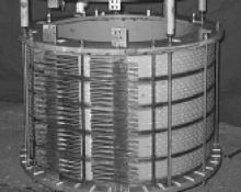
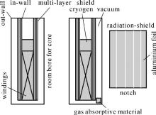
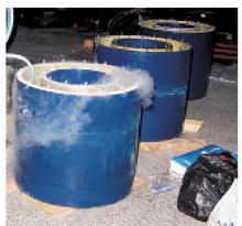
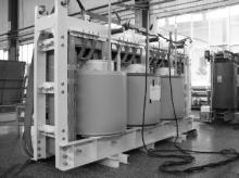
A 630-kVA 10.5 kV/0.4 kV three-phase high temperature superconducting (HTS) power transformer was successfully developed and tested in a live grid. The windings were wound by hermetic stainless steel-reinforced multi-filamentary Bi2223/Ag tapes. The structures of primary windings are solenoid with insulation and cooling path among layers, and those of secondary windings consist of double-pancakes connected in parallel. Toroidal cryostat is made from electrical insulating glass fiber reinforced plastics (GFRP) materials with room temperature bore for commercial amorphous alloy core with five limbs. Windings are laid in the toroidal cryostat so that the amorphous core operates at room temperature. An insulation technology of double-half wrapping up the Bi2223/Ag tape with Kapton film is used by a winding machine developed by the authors. Fundamental characteristics of the transformer are obtained by standard short-circuit and no-load tests, and it is shown that the transformer meets operating requirements in a live grid.